|
|
|
|
FT
8390913
Maj.1: 01.02.16 |
PDF 
|
|
|
FT849 Shower by Adler
|
|
FT844 Shower by Capsi
|
|
FT842 Showcase by Adler (fr)
|
|
|
FT860 aluminium profiles by Adler VF
|
|
FT857 Shower Clip-in-door
|
|
FT855 Shower Walk-in
|
|
FT853 Shower Adler VF
|
|
|
Catalogue hinges and hardware
for glass enclosures :
shower, doors... |
|
|
|
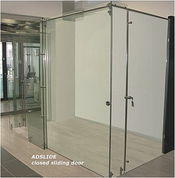
 General presentation :
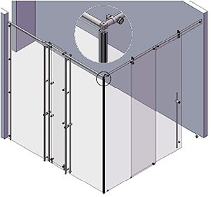
Is a very light and transparent stainless steel suspended track that provides exceptional ranges without any suspension points on the ceiling or stiffeners. This is all thanks to ADLOCK's attachment points: their unique tightening system is now even better. So, the stainless steel tubular rail is placed flush with fixed glass panes and as it will not slide unless several hundred kilograms in weight is placed on it, provides perfect support for sliding doors.
In standard "U" and "L" shaped construction modes with a sliding door, the rail is a window - window or wall - window stiffener: the stiffener can be used on its own to attach, stiffen and secure a glass separating panel. The tube is cut along the whole length of the bay, corrected by the thickness of the intermediate washers on the glass. It is secured through the glass in return by an expandable insert, a clip fitting and a stainless steel screw. It is secured in the wall by a screwed insert held within the tube by the same expandable insert.
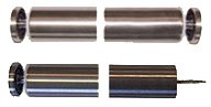
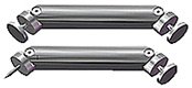
The ADSLIDE stiffeners : |
|
|
|
Stiffener 1m45 in length as standard, possible up to 6m.
ADLER catalogue ref.:
69832F PSS
69834H BSS |
Wall-glass stiffener |
Glass-glass stiffener |
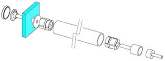 |
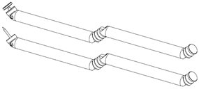
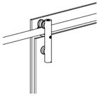
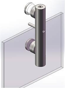
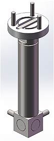
Detailed view of the attachments for a tube with diameters 21x25 into the wall and through a glass pane.
Bracket attachments.
|
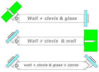
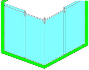
These stiffeners may also be articulated, enabling them to connect to glass panels or a glass panel and a wall which are not perpendicular to each other. In this case, at least one of the links has a special 25 diameter cover. To minimise the size of the cover and to guarantee the full potential and transparency of the assembly, its play angle is limited to 0° - 45°. Note that beyond 45° the stiffener will not provide its full effect.
|
|
|
ADLERcatalogue Réf. :
69833G PSS
69835J BSS |
|
Several partitions in series |
The main self-supporting constructions: |
|
|
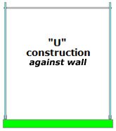
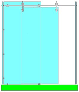
"U" shaped construction - i.e. supported against a wall -:
The front is supported by 2 fixed glass side walls. The tubular rail, whose ends are secured in this way, holds the fixed glass front panel which, in return, brackets and stabilises the assembly. Until the assembly is perfectly rigid, the system still remains flexible, which means that it is also very fragile. Until everything is locked in place, bracketing the fixed glass panels to each other makes the assembly extremely rigid and solid. |
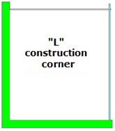
"L" shaped construction - i.e. supported against a corner -:
The tubular rail acts as a stiffener with the fixed side glass panel. Here, anchoring the stiffener in the wall is enough to hold the fixed side glass panel. Nevertheless, surface-mounting the fixed front glass panel on the tubular rail significantly helps stiffen the assembly and reduce the demands on the stiffener's anchor point. This gives a certain advantage to ADSLIDE constructions which avoid placing too much stress on the anchor points, points which are often weak in constructions as they are difficult to control depending on the type of substrate (BA13, plasterboard, concrete, etc. whether or not they are tiled). |
The fixed front glass panel is clipped to the tubular rail, which is supported in the centre by this glass panel. In short, the fixed glass panel on its own supports between 50% and nearly 80% of the door's weight. It also supports any accidental over-loads, such as a person swinging from the rail. For glass panels which are 8mm thick, and have reasonable heights up to 2m40 -, the acceptable width for this type of front panel, without any ceiling suspension or any specific thickness (see § "constructions with greater rise), may reach 2m30 with a door with a width or around 1m20 and an opening of around 1m10. Beyond this, the assembly's stiffness must be checked. |
|
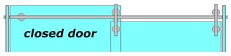
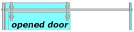
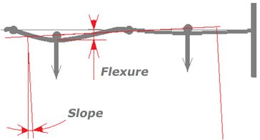
Under the track effect, the rail tube bends between its different attachment points. It is useful to line up the rail attachment points on the glass roller bearings: for aesthetic reasons, as the attachment points - which are already small - disappear behind the roller bearings when the door is in its final positions: open or closed; but also for mechanical reasons, as this minimises the rail bending, the "give" and the door's slope. There is a risk that the give will rub the bottom of the door on the floor or the guide on the floor, thereby blocking or slowing the door's movement. |
The slope causes the door to swing and creates visible additional rubbing, which results from the combination of the door's inertia in its semi-rotary movements and the local rising of the slopes caused by the rail bending. |
|
 |
 |
ADSLIDE is designed and sized to prevent all of these possible problems with sliding doors. ADSLIDE's first clear advantage is that the tube-rail attachment points on the fixed glass panel constitute full, perfectly rigid anchor points, which guarantee perfect stability and tracking once installed and which will stay in place over time.
Specific case of recess constructions: |
 |
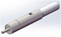
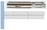
"I" shaped construction, i.e. inserted in a recess -: in this case, the tubular rail no longer holds the side wall; it is pushed into each side wall. These points are firm support points for the ends of the tube. They are composed of an ADLOCK overpanel (socket that receives the upper axis of a hinged door) equipped with a spherical bearing with 5° angular play, which facilitates assembly and compensates for any verticality faults in the wall at the attachment point; and a push insert which must be forced into the end of the rail tube to be cut to measure and which features a retractable axis system - pulled back during insertion between the 2 end overpanels, then automatically spring back when it is opposite the bearing -. The attachments for the 2 overpanels in the recess walls is critical. |
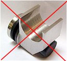
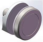
Push insert
and overpanel
|
|
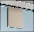
Clip - guide |
|
|
|
|
These parts withstand significant pull efforts: without any accidental over load, 2 to 3 times the door's weight is possible. ADLER SAS recommends choosing screws and pegs that are adapted to the substrate (concrete, brick, BA13, plaster tiles, etc. whether tiled or not) – recommended screw diameter = 6 or 8 mm -; ideally distributing the pull load over the full height of a metal profile glued to the wall and screwed in at several points - the overpanel is then simply screwed in with an M6 metal screw in the profile, which takes the full weight of the door -.
The fixed glass panel is held vertically by claws: miniature clips with a dimension of 20 mm. It is fully locked in place by the guide - clip in the lower bottom corner, in the coverage zone between the door and the fixed panel.
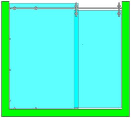
Specific case of surface-mounted constructions: |
|
In the case of a surface-mounted construction, the rail is secured flat on the wall, generally above the door passage. ADSLIDE provides an original solution for this attachment by moving the attachment point above the rail to flush with it so that is it practically invisible but is very easy to screw in. Once in place, this point provides maximum pull resistance; the more weight applied to the rail the more its attachment feet will be pushed against the rail's supporting wall. If the wall is brittle, made from a material which does not does not enable effective pegging ADLER SAS recommends fixing first to the wall (full surface gluing and distributed screwing) a metal flat spot the full length of the rail, which is largely invisible as it is masked in the angle of view by the rail; this flat spot is itself drilled and threaded M5 at 3 points (up to 2m30 total rail length, 5 points beyond this) to screw in the attachment feet that were previously screwed into the rail (M5 screw). |
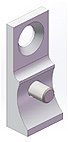
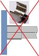
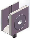
| Attachment foot for a tube - rail with dia. 25 on a wall |
Floor guide for surface-mounted door (*) |
|
|
| (*) also suitable for certain recess, corner, etc. constructions where the fixed glass panel does not come right down, is supported by a wall, etc. |
Constructions with greater rise:
|
Reminder of the standard ADSLIDE system capacities
|
 |
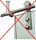
Before ADSLIDE, the construction of a shower cabinet front panel with sliding door required, as soon as the opening width exceeded 60-70 cm, several attachment points on the ceiling, with the fixed glass panel held in place with fairly solid connectors as the tracks themselves could not be reduced in size.
|
 |
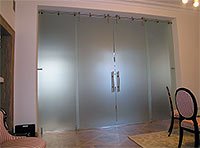
| Thanks to ADSLIDE all of these constraints have been removed. Thanks to the force of the ADSLIDE rail attachment points on the fixed glass panel, up to a width of around 2m30 - as in the case here for cabinets produced for a large hotel - most of the parts have been removed and the others have been reduced in size to produce a transparent and light assembly. |
Before ADSLIDE |
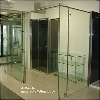
with ADSLIDE |
|
|
|
The ADSLIDE tracks are reduced in size: diameter 30mm, the same as the attachment points. This provides for an extremely even assembly down to the finest details. The track bearing's shape has been optimised to remove any interfering movements and vibration from the door. A single track attachment point on the glass panel is enough: once this point is fully tightened (beyond 20 N.m) it can support at least 3 times the maximum load recommended for each track - 40kg per track -. |
|
 |
All the rail attachment parts, on a glass panel, at the end in the walls of a recess, or surface-mounted, are designed with ADSLIDE to ensure the best resistance for the assembly, simplify as much as possible the design of front panels with sliding doors, minimise the volume and drastically reduce the number of attachment points.
- Better resistance thanks to optimum load distribution with attachments in the rail axis, or above it, rather than below the application point.
- Simplified design: with ADSLIDE everything is contained within 25mm diameters. All systems may connect with each other, including with ADLOCK, with no risk of a door colliding with any protruding parts: rail end attachment, attachment to glass panel and so on. For example, if necessary, including for aesthetic reasons, 2 rails may be secured symmetrically to the same fixed glass panel and, extending from it, suspended from the ceiling or attached to an overpanel, as standard.
- Fewer parts for simpler installation and maximum transparency. |
|
|
With a standard tubular rail with a diameter of 25 mm and a thickness of 2 mm and glass panels with a thickness of 8 mm, the maximum reasonable door width is around 1m20 for any recess, corner or wall mounting: in the specific case of surface mounting, simply increase the number of attachment feet, ideally placing them at equal distance from each other, with those on the end and in the centre aligned with the door's tracks, with the door either open or closed.
If the fixed glass panel and door are of comparable width, the maximum total width of the front panel is around 2m30. Beyond this, the rail begins to bend noticeably and the door's movement is disrupted or even blocked.
In all cases, with glass doors 8 mm thick, one attachment point per metre of rail is recommended, with the end attachments aligned on the corresponding tracks, with the door open and closed respectively. An odd number of attachment points is preferable.
|
A wide range self-supporting front panel
|
|
For a front panel width of over 2m30, if the door width remains less than or equal to 1m20n simply increase the number of rail attachment points on the fixed glass panel. Ideally, the symmetry will be respected in the attachment points on each side of the door and fixed glass panel coverage area. |
When the door is expanded, the tubular rail is not stiff enough. Excess bending is avoided, either normally with ceiling suspension or specifically, which preserves the structure's transparency and lightness with a glass lintel (or overpanel) stapled at several points along the free part of the tube, in the extension of the fixed glass panel, and which solidifies this tube. There must be at least 1m between the stapling points on each glass panel; if possible they must be distributed symmetrically in relation to the edge between the fixed glass panel and the overpanel.
|
|
| Detail of the SAINT-GOBAIN GLASSOLUTIONS show-room in Villeurbanne (69100): |
|
|
The length of the front panel with 2m60 sliding door means that the free part of the rail must be stiffened with an overpanel that is screwed at 3 points. |
|
|
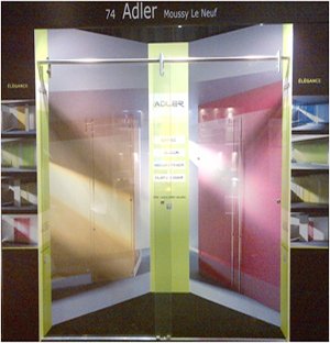
ADLER SAS stand
Architect@Work – Paris - 2012 |
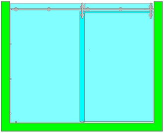
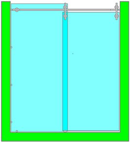
In the previous construction, the double sliding door covers a total width of over 2m15. Each door runs on its own rail: the 2 rails are secured parallel to each other. Neither of the 2 rails, nor the 2 rails connected to each, can support the door weight. They bend a few centimetres when pressed by a finger. They must therefore be supported, ideally at their mid point. A glass strip of around 100mm in width and 8mm thick is placed between the 2 doors, in their coverage area once closed. The rails are screwed on each side, through a wall attachment foot, surface-mounted on this vertical glass strip. This exceptional installation was featured at several trade fairs. The strip stiffens the rails so much that the assembly can support accidental over loads greater than 100 kg, suspended under the rails in either opening. |
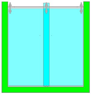
Detail of the SOGIMEX show-room
in Paris (75012): |
 |
In this construction, the sliding front panel is 3m10 long with a door of around 1m60. As shown earlier, an overpanel stiffens the rail in its free part (not including the fixed glass panel). There is still then the problem of stiffening a front panel over 3m long and 2m50 tall, in single glazing 8mm thick. The glass stiffening beam principle developed for ADLOCK self-supporting partitions is transferred here as a vertical stiffener. The double wall screwed tightly to the middle of the fixed glass on the sliding front panel practically cancels out any bending, and therefore any vibrations, over the full height of this fixed glass panel. The anchoring of the assembly in the ground and the weight of the beam once formed significantly reduce any possible pushing-in of the front panel under perpendicular pressure. |
|
|
| A wide variety of constructions: |
ADSLIDE combines intelligently with ADLOCK to enable the most varied range of constructions, in addition to the options outlined above:
- Double corner doors with cubic angle return: possible for doors with a maximum width of 0m50 with no ceiling load recovery;
- Similar construction for doors up to 1m20 with angle return and suspension of the corner part under the ceiling. |
 |
|
|
Construction of an "L" shaped cabinet - in a corner -: no ceiling charge recovery, or by any special glass construction, door width limited to approximately 0m50.. |
 |
|
The double door construction hardly varies at all from the construction with a single door at the front and a side return in glass stiffened by a stainless steel tube. |
Attachment under the corner return cube ceiling is a natural way to support the doors' load and increase the range of a corner cabinet.* |
|
|
|
|
(*) ADLER SAS's design office is at your disposal for any specific corner cabinet or partition design, with very wide double doors, possibly with no ceiling attachment. For example, combined solutions with rail stiffening by overpanels, themselves supported at an angle by the fixed glass panels thanks to glass beams for example are possible.
|
| "Commercial plans" have been designed for various recurring constructions, detailing all the components and enabling glass plans to be drawn up quickly and flawlessly from parameter diameters and customer readings. Consult ADLER SAS. |
THE DOOR STOPS |
Stopping sliding doors is critical in most constructions. If the stop point is at the upper part of the door, for example, by stopping the door by holding back the tracks this will lead to the door tipping over as it "wants" to continue moving. If this movement is free, then the door may drop out. |
So, the door is generally not free and is even significantly limited by additional stops, double track under the rail and so on: the inertia efforts used and the lever arm (ratio between the door height and a characteristic rail and track height) leading to extreme demands on the track mechanics and, by reaction, the rail's attachments. Nothing can withstand this; everything will loosen very quickly; this system may operate for a long time unless it is very large, as is the case in good aluminium hidden suspended track solutions. |
|
The other solution, which is perfect in mechanical terms, involves stopping the sliding door at its full height, so distributing the impact pressure and avoiding any interfering movements; but this is rarely easy to implement as the tempered glass doors are often curved as well as being guided with a lot of play and the walls which act as stops are rarely flat and vertical. With ADSLIDE, ADLER SAS has re-examined door stop solutions: to solve all of these problems while designing a partition with sliding door, and to guarantee the installation's safety over time, ADSLIDE door stops are ideally positioned in the middle of the door in the centre of gravity. They remain very discreet. A short, sharp stop impact sees the door bounce back; a soft impact with a bounce is less noisy; ADSLIDE's stops are a compromise between these two extremes. |
 |
 |
|
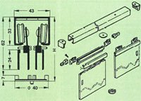
List of the main metal parts used to build cabinets with sliding doors
25x21 diameter stainless steel tube reference: 60057F before length cutting, drilling and tapping, 60058G and 60059H depending on the type of construction (see Commercial plans). |
|
|
|
|
60006Z – Ceiling attachment
(for 2 door corner cabinet)
|
60008B – Rail/Glass attachment |
|
|
|
|
|
|
|
|
|
|
|
60000T – Recess attachment (x2) |
  |
|
|
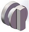
60002V – Attachment and door middle stops (x2) |
60034F – Wall and door middle stops (x2) |
|
|
1979 |
Suspended track – runner glued to the glass door |
|
1984 |
Distribution of the HAWA range of suspended tracks for glass |
|
2006 |
Launch of the INOVAGLAS stainless steel trackrange |
|
2012 |
Launch of the INOVAGLAS stainless steel track range |
 
Z.A. La Barogne - 9, Av des 22 Arpents - 77230 Moussy le Neuf - France
Tel.: +33 (0)1.60.03.62.00 - Fax : +33 (0)1.60.03.62.49
E-mail : admin1@adler-sa.com - Site : www.adler-sa.fr
SAS au capital de 2 014 000 euros . RCS Meaux
|
|