|
|
|
|
FT
828b.rév.2 0414 |
Télécharger
et imprimer cette fiche.
Download
and print this technical data sheet.
|
|
|
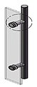
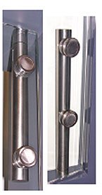
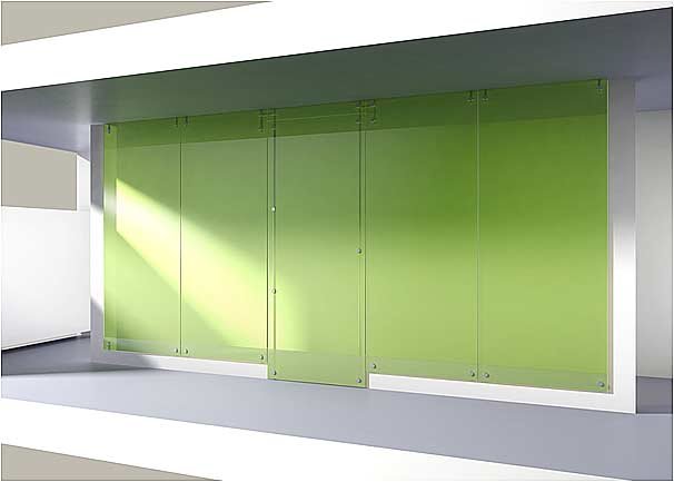
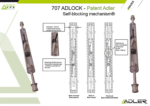
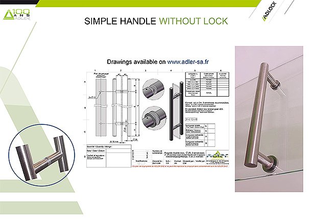
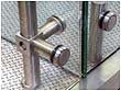
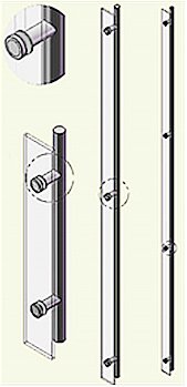
ADLOCK is a complete range of brushed or polished stainless steel tube door handles, hinges and connectors, in diameters of 20, 25, 30, 35, 40 or 45 mm. It uses several ADLER SAS patents for extraordinary glass hold (30 mm diameter ADLOCK points with one M8 screw to be tightened fully), such as for the auto-locking security mechanism.
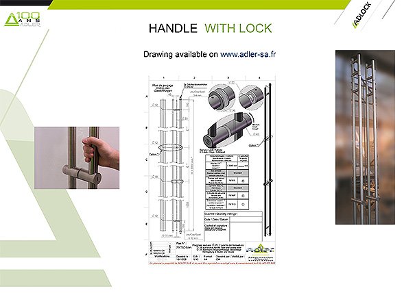
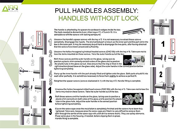
The single or double handles have a number of spacers. They may integrate a security lock or a simple button or triangular key lock to name just a few, with many combinations of these solutions. They may be short or full door height; attached vertically or horizontally like a towel rail.
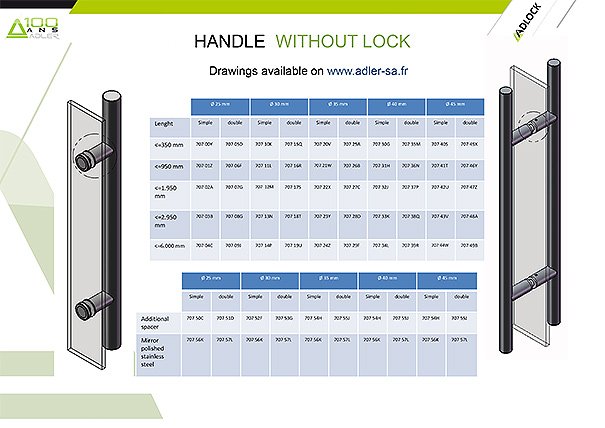
Variety of handles without lock:
|
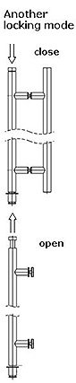
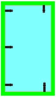
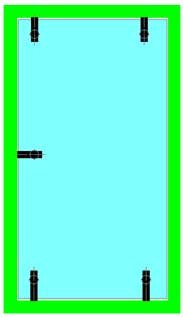
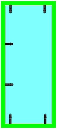
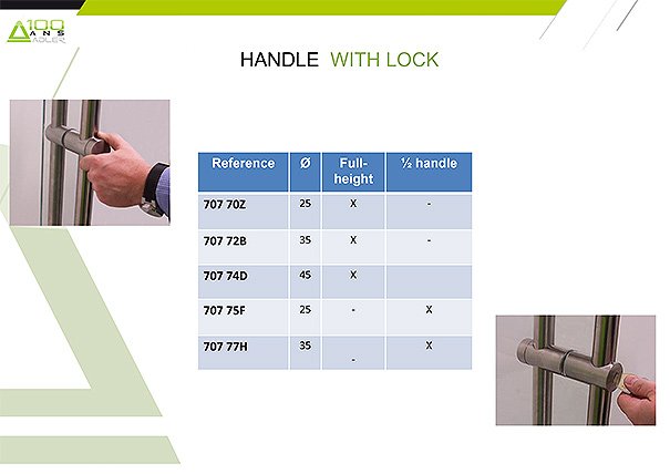
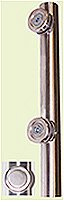
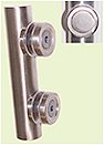
Example of handles with integrated lock: in diameter 25, 35 and 45 mm
| With handle without lock |
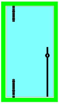
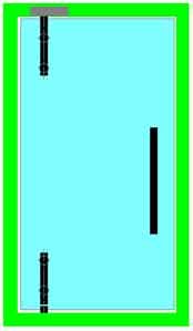
With handle with lock integrated, 1 single locking point (low) |
With handle with lock integrated, 2 locking points (high and low) |
|
|
|
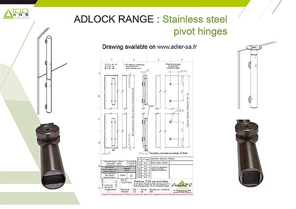
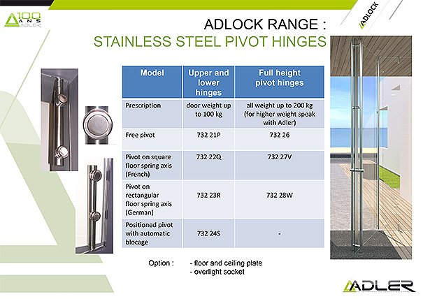
Same construction as before but with hinges on door brake: with square (French) or rectangular (German) axis; adapting to SEVAX JANUS or TS or DORMA BA door closure; with standard aluminium insert for recalls up to force 3; or reinforced in stainless steel and double screwing point on the door up to force 6 (for example for SEVAX Janus F5 or Dorma BTS 80). |
|
JANUS from SEVAX.
The door is then hinged around a free pivot at the bottom and fixed to an upper pivot containing an insert adapted to lintel pivot (straight and not conical axis).
The ADLOCK hinges (still with 25 mm*) can also take a lintel pivot for example All of these variants are specific articles or are simply options to be ordered as the same time as the hinges. |
|
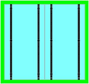
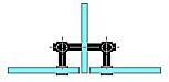
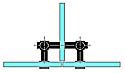
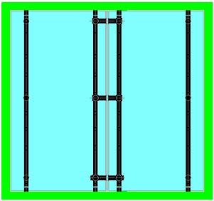
Full-height hinges: For heavy or very strong rake doors, or doors that are very wide, it is strongly recommended and often necessary to use full-height hinges. This specific construction enables:
- The door weight to be distributed, plus the extra load imposed by current DTU standards (+100kg at the end of the door in Class 4, the most strict) across all of the door's screwing points when only the low hinge points are used in the case of short hinges; with the same total number of attachment points (at least 2 low, 2 high in the case of short hinges, i.e. 4 in total), the acceptable door weight with a full-height hinge is doubled;
- The door to be stiffened significantly, so constructions to be made with very strong rake for which traditional "Clarit" type hinges are not suitable - the door vibrates at the top with the slightest stress, leading to choppy rotation, often a slippage of the glass in the hinges, even early destruction of the ground pivot and so on - where professional rules recommend the use of very thick glass - which becomes useless - ;
- Through the ADLOCK attachment points, significant shearing to be supported (up to 130 kg per point) so very heavy and extraordinarily large doors.
For example, among recent installations produced with this type of hinge, we can mention 230 kg doors in tempered 12.12.4 (height 3m x width 1m30); 250 kg in 15 mm tempered monolithic glass (height 3m40 x width 2m20); or even 320 kg, 3m87 tall and 2m70 wide.
The inserts are the same as for the short hinges and enable the same installations.
These tailor-made hinges - their height is related directly to the door height - are produced as standard in 25 mm. They may be produced on request, as a special manufacture, in 35 or 45 mm diameter.
|
| (*) Advantage of the 25 mm diameter for ADLOCK hinges: |
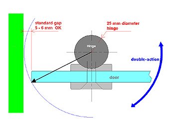 |
The 25 mm diameter is enough and is necessary to accommodate any square or rectangular floor pivot axis. It enables standard play to be maintained between the door and the attachment (wall or frame) of around 6 mm. A greater hinge diameter, for example 45 or 50 mm, means this play must be doubled, becoming, with around 10-12mm, both less attractive in appearance and less functional: thermal, sound and other insulation. |
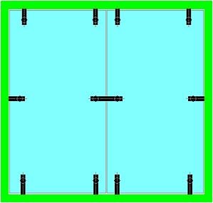
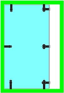
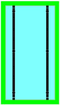
| Examples of installations with full-height hinge: |
 |
 |
 |
 |
 |
 |
In the case of very heavy doors, or doors that close automatically thanks to a force 4, 5 o 6 ground pivot, the low attachment point needs to be doubled. For reasons of appearance, but also because in these cases the doors are also generally very wide, the high attachment point also needs to be doubled. When the central attachment points contribute directly to supporting the weight of the door and the extra load: more weakly in countering the door's overhang. They are also used to stiffen the door very effectively; this point is very effective in the case of strong rake or where a ground pivot is installed. They may therefore be positioned at will, according to criteria which are often to do with appearance: alignment on the handle spacers (**) or on the connectors between the frame and the wall, and so on. |
|
(**) The handles have at least 2 spacers. As standard, ADLER SAS recommends adding an extra spacer when the distance between 2 spacers exceeds 1m40. This distance may be increased in the case of handles with larger diameters (35, ideally 45 mm), especially if they are strengthened by a stiffener insert; or in the case of irregular and precautionary use.
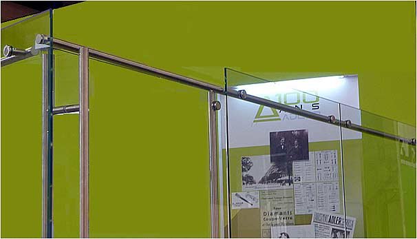
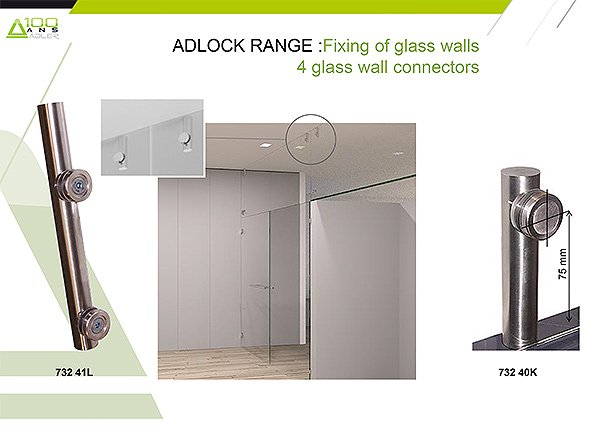
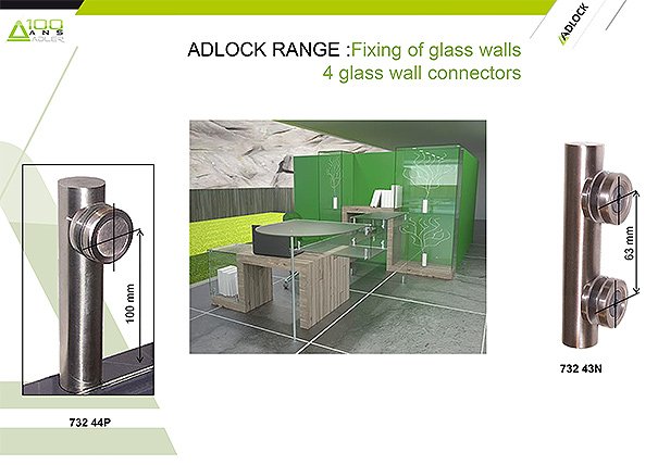
Installing a fixed glass (frame, partition, etc.):
All traditional installation modes: plinth profiles, ground, wall or ceiling rabbets, etc. are possible and may blend in seamlessly with very large doors, ideally ground-ceiling, without over panel thanks to the advantages offered by ADLOCK hinges and handles.
It is also possible to use the connectors in the ADLOCK range, which offer numerous advantages: |
- an even and naturally harmonious construction
- the high effectiveness of ADLOCK tightening points;
- possible adjustments making it easier to install partitions and frontages. |
 |
|
 |
Original partitions may be made by stapling the glass to the full-height hinges. Several hinges may then be secured to a glass; they will lose their pivot effect must give the glass extreme stiffness in its height, which may be outside the standard.
The full-height hinges, like the simple connectors, may be glued to the glass (distance between the surface of the panel and the interior of the tube = 2.5 mm) or separated from the glass thanks to spacers similar to those on the handles (distance between the surface of the panel and the inside of the tube = 40 mm). In this second case, the structure's stiffness is increased further, cleaning is made easier and its appearance is also original. |
|
|
|
|
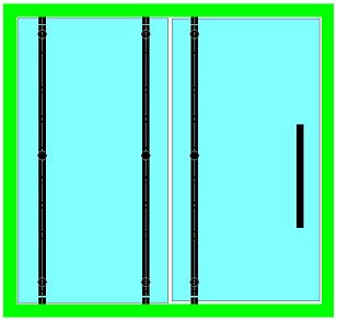
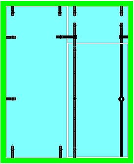
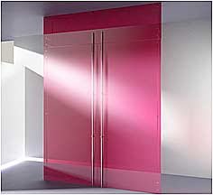
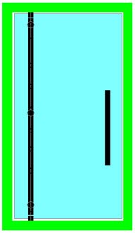
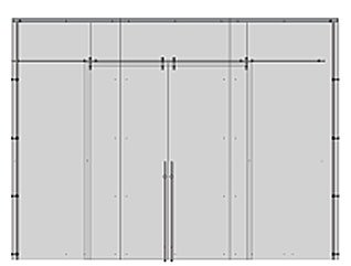
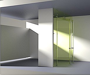
| Creating simple partitions or frontages: |
|
|
This particularly original construction model is recommended in the case of large heights. The fixed panels and doors may also be very wide.
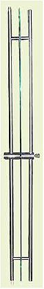
It is desirable to fit the door with a full-height handle. |
All fixed panel or frame attachment modes are suitable for this type of construction.
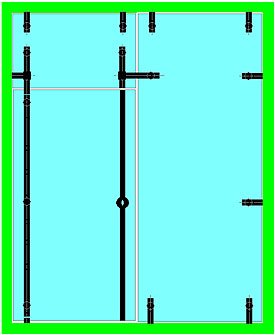
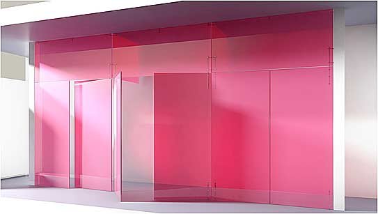
Naturally, the construction may be completed by a second fixed panel, as shown below … |
|
|
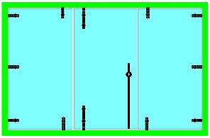
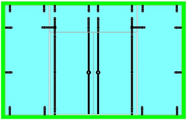
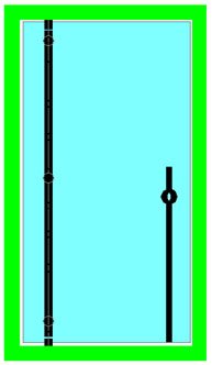
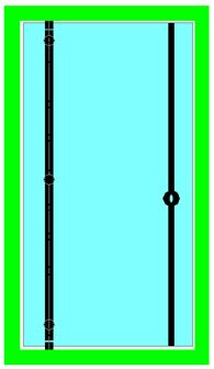
| Creating partitions or frontages with over panel : |
|
|
The centre plate (upper pivot) and striker attached to the over panel link the door to the over panel at 2 points (ideal case for a full-height handle with integrated lock). If there is a hinge on the door frame side, a connector goes from the centre plate and connects the over panel to the frame. In this case, all the connection parts are glued to the glass. |
|
The striker which is useful for a full-height handle with integrated lock and 2 point closures forms a handle which extends the door's own handle. The tube that forms the striker is then fixed to the over panel via a spacer and is separated by 40 mm. The link with the door frame is made via an offset connector. |


|
|
Construction of glass volumes:
In order to complete and expand the previous frontage constructions, a few elements can be used to naturally connect glass panels that are attached to each other, as standard at 180°: 180° glass-glass connectors. |
|
|
In this type of construction, thanks to the stiffening effect of the full-height "hinges", ADLER SAS does not recommend linking the different elements of a partition to each other.
However, in the case of simple connectors, glued against the glass or offset, to prevent any flapping of one glass panel in relation to another, it is strongly recommended to link 2 glass panels to each other at several points across their height, according to the free height and thickness of the glass panels: around 1 m free between each point.
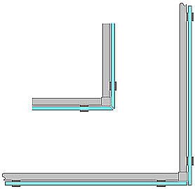
The glass volumes, starting from a fixed point or frontage as above, integrate returns which are generally made of glass: for example, a brace or the starting point of a partition, as standard at 90°. |
|
|
|
This type of construction enables all types of partition to be produced freely, without form constraints. |
Preferably with offset attachments (40 mm spacers as standard), the same hinge in the corner can be used to connect 2 elements perpendicular to the partition.. |
The same connections can be produced if short connectors are preferred. |
 |
|
|
In the case of a brace or following partitions, the previous constructions are available in symmetry.
|
 |
 |
|
The square glass with the partition may exit on the frontage |
or be supported on the partition. |
|
NOTE: ADLER SAS has several solutions to seal these frontage elements: auto-adhesive "bumper" seals to glue to the edge of one of the two panes of glass and pressed automatically between adjoining frontage elements the same as recommended for the
seal in the lower section, or the upper section of the partition); or L-shaped PMMA profiles which are also self-adhesive and completely transparent. All of these products are highly UV ray-resistant.
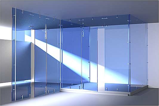
Construction of "free-standing" glass volumes: "Free-standing" here means glass constructions which are not -or very little at least - supported by solid partitions (walls, posts, metal structures, etc.) and which are not attached to the ceiling.
The stiffening principle of the full-height hinges, used earlier for large doors, is used again here, but horizontally this time, to ensure the cohesion of the whole construction A horizontal tubular structure links all of the constructions panes of glass; the assembly (tubes & glass) forms a very rigid structure that does not lose its shape. |
 |
The panes of glass are stapled to the horizontal tubes using ADLOCK attachment points. They support the glass panes while the tubes hold them in place vertically. These tubes form stiffeners (such as shower wall stiffeners) for which they use the wall, bracket (start point 90� from the wall or pane of glass) or angle (90� to 45�) attachments. 2 tubes may be bracketed extremely strongly to each other via a link cube. They may also be linked at a free of angle of 90� to 45� using the same quick link as used to secure a stiffener to the wall or a pane of glass. |
 |
|
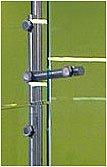
Special attachment with cube to link the stiffener tubes to each other and staple the glass. |
Special attachment with cube to link the stiffener tubes to each other and staple the glass. |
If the volumes constructed are very large (typically over 2 m in dimension), it may be necessary to stiffen the structure further as the combined stiffness of a pane of a glass and a firmly stapled tube is not enough. More solutions are always available; the choice depends mainly on aesthetic and/or budgetary considerations: (1) To thicken the glass,
or; (2) Stiffen the tubular structure. As for thickening the glass, the solution involves using current standards, especially those produced by professional rules: the additional cost is generally significant and there is a notable increase in the weight of the glass, bringing installation difficulties. The tubular structure may be stiffened in several different ways:
|
 |
 |
 |
A first stiffening effect is obtained by separating the tubes from the glass ("offset connectors"). |
The previous effect remains low. It may be increased significantly |
To maintain the transparency, of the structure, the stiffeners may also be stiffened using glass stiffeners. |
These are then stapled directly to the stiffening tubes, or are offset again, like the frontage, using standard 40 mm spacers. These solutions may be combined at will.

Examples of ADLOCK self-supporting partitions:
A number of large-span self-supporting partition systems have been designed providing free lengths of up to 10 metres or more with more-or-less standard assemblies. Naturally, the overall stability of the assembly requires fairly significant bracing to be provided at the ends of the partitions, possibly even angles in the case of continuous partitions, or else a connection to a wall or a sturdy column.
Example 1: horizontal rigidity is provided by a fairly stiff metallic beam straddling the partition, supported by double handles forming posts, that are attached to the glazed panels and restrained by the beam in the direction perpendicular to the plane of the partition. The glazed panels are mutually independent, and are each stiffened by the two double-handles that connect them to the upper beam. One handle of each double-handle assembly is also fitted connected via stud to the floor, the other handle being simply attached to the first through the corresponding glazed panel. The upper beam is typically 140 mm wide (2x25+2x40+10) and 50 mm high. The standard handles are 10 mm thick. A glass thickness of 10 mm is also generally sufficient. 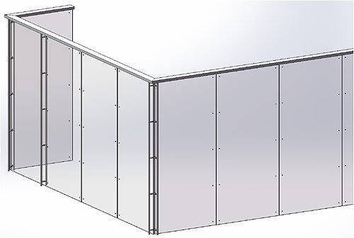
|
|
2 Example : Although similar to the previous example, this solution differs in that the horizontal stiffening beam is no longer supported above the partition by handles forming columns, but directly supported on the glazed panels themselves. The glazed panels are firmly secured by ADLOCK points mounted on the beam that is itself supported by the glazed panels. The assembly can be adequately stiffened by means of corner posts consisting of pairs of full-height 25 mm diameter double handles, the inner handles of which are combined to form a single vertical tube. This tube can be fixed into the floor and to the underside of the upper beam. The example illustrated below includes an ADSLIDE sliding double door. |
 |
 |
The 3rd example of a large span self-supporting partition is the boldest, most original and most transparent of the three solutions briefly described here. The stiffening beam is no longer metallic, but made of glass. However, unlike the glass stiffener described previously (page 10), the glass stiffening elements, which form a kind of over-panel, are vertical instead of horizontal. The main advantage of this is that dust and other dirt cannot build-up on the glass stiffeners, and the structure is therefore simpler to maintain. In the following "standard" assembly, the glass partition panels and stiffening element(s) forming "over-panels" are very securely connected together by 30 mm diameter, 68 mm long spacers. The entire range of ADLOCK components can therefore be used without modification to connect perpendicular panels, for attaching the socket and the upper lock strike of a full-height handle with in-built lock, etc. The stiffening effect of these beams is very impressive and depends directly on the tightening torque applied to each ADLOCK fastening point. To ensure significant stiffness, each point must be tightened to a torque of more than 24 N.m. A higher tightening torque (of the order of 36 N.m) will increase the stiffness of the beam correspondingly – NOTE: such a high tightening torque is only possible using metal washers that are available from ADLER SAS, as the plastic washers of the ADLOCK range would yield under such a high load. Assembled in this way, a 3 m long beam can resist a concentrated load of 50 to 60 kg applied at the centre of its span and acting perpendicular to its plane. Deflection under this load would be small, of the order of one millimetre, and would be perfectly elastic, meaning that it would disappear as soon as the load is removed.
|
|
| Hinging and locking of the ADLOCK doors in a free-standing structure :: |
 |
The door pivot's over panel is inserted into the tube. All efforts are applied to the tube axis. No rotation movements are applied to the tube, which therefore does not tend to loosen over time.
By construction, as all the glass panels (doors, fixed panes, etc.) are stapled to tubes that are assembled in the same length, even very long partitions are easy to construct and do not require any specific alignment. Everything is perfect by construction.
|
|
|
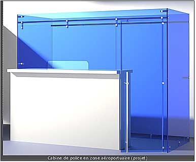
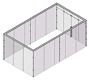
"Completely free-standing" constructions »…
Completely free-standing, a glass construction is no longer anchored to the ground. The whole structure then needs to be secured to flat profiles of the desired width. ADLER SAS recommends as standard profiles that are 37 mm wide and 5 mm thick. Other profiles from the ADLER range, which are generally recommended to make up for wall flatness or verticality faults when building shower cabins with swing or sliding doors, may be used cleverly to provide ground profile support. As with walls, they can be used to get around floor flatness and level faults. Pre-machined to construction dimensions, they enable very quick, perfectly in-line assembly, without dragging or jamming. Significant installation time is saved; the installation quality is naturally perfect: glass alignment, play adjustment and so on. Long-lasting construction is guaranteed. |
|
The cabinet opposite is perfectly static and extremely stiff. It is very simple and quick to construct: positioning of the 2 side panels and attachment of the 2 stiffeners: then stapling of a frontage glass - everything now holds in place; finishing of the stapling of the frontage elements, then clicking in of the door; marking then drilling of the integrated lock handle striker; sealing of the trigger in door locked position.
Installation is even quicker if flat pads are positioned on the ground for the low connectors to be attached.
Police cabine in airport area |
To find out more, in pictures …
|
|
Entrance to the ADLER SAS showroom |
|
Element of an internal frontage in an airport |
|
|
Other internal frontage element |
Brace for the frontage of a large store (project) |
|
Frontage of a large store (project) |
|
Internal layout of a bank |
 |
|
Traditional frontage |
Mid-hinge, mid butt hinge: low pivot and high wall attachment |
|
ADLER SAS stand at BATIMAT 2011 - Paris |
| |
|
Product and patent presentation
|
|
 |
ADLER
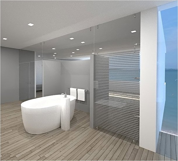
L’Hôtel de la Plage |
|
|
|
|
|
|
|
|
|
|
De façon générale, les pentures comprennent des points de fixation directement usinés dans le tube penture (généralement fluo-perçage et fluo-taraudage pour les diamètres les plus petits) et d’autres compris dans des inserts d’extrémités qui peuvent tourner plus ou moins librement dans le tube penture et donc s’orienter perpendiculairement à la glace lors du serrage. IL FAUT TOUJOURS fixer les points centraux (ceux usinés dans le tube) avant ceux d’extrémités : SINON RISQUE IMPORTANT DE CASSE DE LA GLACE AU SERRAGE, voire de desserrage prématuré en fonctionnement.
IL N’EST PAS POSSIBLE DE REGLER LA POSITION DE RAPPEL DE LA PORTE AVEC LA PENTURE, en particulier la position angulaire de l’insert lors de son serrage. Le réglage de position angulaire ne peut se faire que par l’ajustement et l’immobilisation du ferme-porte dans son boîtier ou dans le linteau.
Sur Pivot Libre :
La penture doit être fixée sur la glace en partant toujours des points centraux (ceux situés vers le centre de la glace) pour finir par les points extrêmes (ceux les plus proches des chants haut et bas de la glace) ; la glace étant libre de toute tension, flexion,… posée verticalement sur son chant libre (celui opposé à la penture) voire à plat sur un support plan.
Ainsi équipée, la porte est dressée puis la penture insérée dans le pivot préalablement inséré dans le sol ; enfin l’axe haut rétracté puis relâché, éventuellement ressorti puis immobilisé pour s’enficher dans la crapaudine (pivot haut) – Cf. notice d’utilisation -.
Pour régler la position de la porte (ajustement des jeux haut-bas et gauche-droite), lever légèrement la porte avec un levier de calage (Réf. 182 14Y) ou des coussins gonflables (Réf. 186 50X) en veillant à ce qu’elle ne touche ni mur ni autre paroi fixe,… ; glisser les cales ajustées et reposer la porte sur celles-ci ; relâcher les vis de fixation de la porte sur la penture (sans les desserrer complètement) ; ajuster la position de la porte sans que les vis de fixation viennent à forcer sur un des bords des trous de fixation de la porte ; resserrer les vis à bloc (consigne standard = 20-24 N.m) ; relever légèrement la porte, ôter les cales et redescendre la porte doucement jusqu’à la libérer. Valider le bon fonctionnement (attention lors de la 1ère rotation au jeu côté penture !). Si besoin, réitérer l’opération.
- Sur Ferme-Porte :
Pivot de Sol :
Dans le cas d’un pivot de sol, l’opération est comparable à celle décrite précédemment dans le cas d’un pivot libre. MAIS LE PIVOT N’EST PAS LIBRE. IL CONVIENT DONC D’IMMOBILISER ET D’AJUSTER LA POSITION DE LA PORTE UNE FOIS CELLE-CI PLACEE NATURELLEMENT (c.-à-d. LIBREMENT) DANS LA POSITION DE RAPPEL DU PIVOT DE SOL. Au besoin, faire jouer préalablement la porte plusieurs fois, dans un sens puis dans l’autre, pour qu’elle se place bien dans le plan de fermeture imposé par le ferme-porte. Ce pivot aura donc préalablement été réglé pour que le plan de fermeture de la porte soit celui attendu ; et IL AURA ETE IMMOBILISE dans son boîtier. Quand la porte est assurément arrêtée dans sa position de rappel, la caler comme précédemment et procéder aux réglages comme précédemment.
Pour bien réfléchir, retenir que l’insert bas est en prise sur le pivot de sol (ferme-porte) et restera aligné sur l’axe de fermeture de ce ferme-porte. S’il n’est pas dans le même temps parfaitement d’équerre avec le plan de la porte, le serrage ne pourra se faire correctement, au risque : de casser la porte lors du serrage ; ou de voir le serrage se relâcher précocement, dès un nombre limité d’ouvertures-fermetures.
Pour assurer le réglage, une fois celui-ci conforme à ce qui était souhaité, faire jouer la porte en l’ouvrant alternativement dans les 2 sens une dizaine de fois. Vérifier que l’ajustement de la porte est toujours correct. Laisser la porte se refermer, la caler simplement par sécurité et vérifier le couple de serrage des vis basses de la penture. Si un desserrage est observé par rapport au couple de serrage assuré précédemment, resserrer, libérer le calage et réitérer cette opération. Sinon, la porte est correctement réglée et fixée.
Pivot en Linteau :
Dans le cas d’un pivot en linteau, les principes précédents restent valables.
L’utilisation de pentures courtes avec 3 points de fixation (en haut et en bas) est vivement recommandée. Pour le montage, la penture basse est préalablement fixée sur la glace (points de serrage hauts – les plus centraux – fixés en premier, le point bas – celui pris dans l’insert du pivot libre – étant serré en dernier pour l’auto-alignement sur les 2 autres points). Puis la porte est dressée et plantée sur le pivot de sol et calée dans cette position (épaisseur de cale correspondant au jeu théorique prévu, voire augmentée d’un millimètre). Le pivot haut est alors enfiché en force sur l’axe du pivot en linteau ; les 2 vis inférieures de fixation de la porte sont serrées à bloc ; la vis supérieure (celle prise dans l’insert rectangulaire haut) ne sera vissée qu’après avoir libéré la porte de son calage au sol et vérifié qu’elle tourne relativement librement et sans rappel autour de la position de fermeture attendue. Approcher alors la vis de serrage supérieure et constater que la porte s’aligne progressivement (et très faiblement) au long du serrage sur la position de rappel du ferme-porte. Serrer à bloc la vis. Faire jouer une dizaine de fois la porte. Vérifier que les vis de serrage de la penture haute, en particulier la plus haute, sont toujours serrées au couple nominal.
- Serrage des pentures :
Se référer aux notices de pose.
- De façon générale, dans le cas de pentures sur pivot libre, les points de fixation doivent supporter le poids de la porte, retenir le dévers du fait de la fixation en porte-à-faux de la porte et la surcharge –jusqu’à 100 kg suivant la norme en vigueur – possible en extrémité de porte. Un serrage habituel pour pièces ADLOCK, avec rondelles plastiques transparentes ADLOCK, à 20-24 N.m doit suffire. La forme de la penture (pleine hauteur ou courte), le nombre de points de fixation… dépendent des dimensions et de l’usage pressenti pour la porte.
- Pour les pentures sur pivot de sol, le type d’insert et le nombre de points de fixation sur l’insert dépendent également du pivot de sol choisi. Plus celui-ci est puissant, plus l’insert doit être résistant et plus le nombre de vis liant la glace à l’insert planté sur le ferme-porte doit être important pour transmettre de la porte au ferme-porte ou réciproquement le couple de fermeture / d’ouverture.
. Dans le cas de portes standards, avec ferme-porte en Force 3, un insert en aluminium avec un point de vissage et des rondelles de serrage en plastique suffisent. Le couple de serrage prescrit est entre 14 et 18 N.m.
. Dans le cas de ferme-portes en force 4, voire 5 avec usage occasionnel, un insert renforcé est prescrit avec au moins une vis de serrage (la basse). La vis peut être en inox A4-80, idéalement en acier traité 10.9. Les rondelles de serrage sont nécessairement métalliques : en aluminium. Le couple de serrage prescrit est de 24N.m.
. Dans le cas de ferme-portes en force 5 pour usage intensif, et en force 6, il faut un insert renforcé fixé avec 2 vis en classe 10.9, des rondelles métalliques (aluminium) et un serrage au couple nominal de 34 N.m.
. PAR SOUCI DE SIMPLIFICATION par homogénéisation des consignes, retenons que sur tout pivot de sol, les pentures sont équipées de rondelles en aluminium, de vis Classe 10.9 traitées anticorrosion et que le couple de serrage est au minimum de 24 N.m, impérativement de 34 N.m dans le cas d’un montage sur pivot de sol en force 6.
Le réglage de position de fermeture de la porte se fait EXCLUSIVEMENT par l’ajustement du pivot de sol dans son boîtier. Aucun réglage n’est possible au niveau de la penture et de sa fixation.
- Les pentures en linteau sont limitées pour un usage en force 3 ou 4 en standard. Elles peuvent encore convenir pour un usage occasionnel avec force 5. L’insert est toujours en inox, avec un seul point de fixation. Selon les règles définies pour la fixation d’une porte sur un pivot de sol, il est retenu que la fixation se fait exclusivement avec des vis de classe 10.9 traitées anticorrosion fournies par ADLER SAS, serrées au couple nominal de 34 N.m, avec des rondelles de serrage métalliques (aluminium).
Aucun réglage de position de fermeture n’est possible au niveau de la penture et de sa fixation. Contrairement au pivot de sol, généralement aucun réglage n’est prévu pour le pivot dans son boîtier. Il convient donc de concevoir des points de fixation adaptés du pivot dans le linteau pour qu’ils laissent la possibilité de régler éventuellement la position de fermeture.
Dans le cas d’un fonctionnement en simple effet, le plus simple et le plus s�r consiste � fixer les pivots en linteau l�g�rement d�sax�s – environ 2� vers l’int�rieur, au-del� de la but�e de fermeture voulue -. En premier sont fix�es les portes sur leurs pentures ; seulement une fois l’ensemble r�gl� (vitesse de fermeture…), les portes sont r�-ouvertes et leur but�e commune fix�e. En fonctionnement normal, les portes viennent alors se fermer de fa�on tr�s amortie sur cette but�e qui garantit leur alignement parfait entre elles.
|
| |
Selection of articles |
Buit-in lock handles |
|
|
|
 |
|
|
|
A |
B |
 |
|
|
|
C |
D |
E |
F |
G |
H |
I |
J |
K |
A |
|
Floor locking system (hole to hole320 mm) |
B |
|
Floor locking system (hole to hole120 mm) |
C |
|
Floor locking system Adlock (hole to hole 320 mm) |
D |
|
socket for Adlock integrated handles |
E |
|
Transom's socket Ø35 |
F |
|
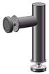
Self-blocking mechanism Adlock Ø25 |
G |
|
Floor/ceiling lock system Adlock |
H |
|
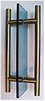
Handle with upper and lower lock Ø 25 |
I |
|
Handle with upper and lower lock Ø35 <=3000 |
J |
|
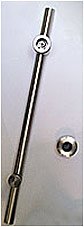
Built-in lock handle Ø25, floor bolt, L=1125 |
K |
|
Single push-type floor lock system Ø25, height 500 mm |
L |
|
Cylinder without key TECYC-ADLER |
M |
|
Key for lock TECYC-ADLER |
N |
|
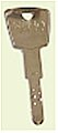
Cylinder without After sales Service key KESO 2000 |
O |
|
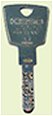
Cylinder with 3 keys KESO 2000 S Ω |
P |
|
KESO, key for lock 2000 S Ω |
Q |
|
Key, After Sales Service, for lock KESO 2000 |
Handles |
|
 |
 |
|
AA |
AD |
|
|
AB |
 |
AC |
AE |
AF |
AG |
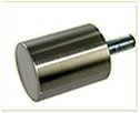
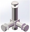
AA |
|
Knob Ø30x40 with threaded rod M8x50 |
AB |
|
Pull handle Ø40 x Ø30 x 6.5 with threaded rod |
AC |
|
Wrench |
AD |
|
Double handle Ø20, L=300 |
AE |
|
Double handle Ø25, L=500 |
AF |
|
Single handle Ø25 <=350 |
AF |
|
Single handle Ø25, 351-950 |
AG |
|
Double handle Ø25 <=350 |
AG |
|
Double handle Ø25, 351-950 |
AG |
|
Double handle stainless steel Ø25, 951-1950 |
AG |
|
Double handle stainless steel Ø25, 1951-2950 |
AG |
|
Double handle stainless steel Ø30, 1951-2950 |
AG |
|
Double handle stainless steel Ø35, 351-950 |
AG |
|
Double handle stainless steel Ø35, 951-1950 |
AG |
|
Additional spacer for double handle Ø 25 mm |
AG |
|
Additional spacer for double handle Ø 30 mm |
- |
|
Mirror polished finish of double handles |
Connectors |
|
|
|
|
|
AH |
AJ |
AM |
AN |
|
|
|
|
AI |
AK |
AL |
AO |
AP |
AH |
|
90° angle connector with 1 mounting point, 76 mm, tube Ø 25 mm |
AI |
|
90° angle connector with 1 mounting point, 123 mm, tube Ø 25 mm |
AJ |
|
90° angle connector with 1 mounting point, 76 mm, tube Ø 25 mm90° angle connector wall/glass with 1 mounting point, 76 mm, brushed stainless steel tube Ø 25mm |
AK |
|
90° angle connector glass/glass with 1 mounting point, 76 mm, tube Ø 25 mm |
AL |
|
90° angle connector with 2 mounting points, tube Ø 25 mm |
AM |
|
180° glass/glass connector, 76 mm, tube Ø 25 mm |
AN |
|
Connector Adlock adjustable angle gl/gl 2 mounting points |
AO |
|
Screw Inovaglas Ø 29 in stainless steel M10x3 |
AP |
|
adjustable wall-mounted supports |
|
Pentures |
|
|
|
|
|
|
AQ |
|
AR |
AS |
|
|
 |
|
|
AV |
|
AW |
AX |
AY |
AT |
AU |
AQ |
|
Upper and lower hinge set Ø 25 |
AR |
|
upper and lower hinge set Ø 25 with upper pivot box, french square |
AS |
|
Pivot for transom |
AT |
|
Set of Ø 25 full-height hinge |
AU |
|
Hinge Ø 25, adjustable length, German rectangular axisE |
AU |
|
Hinge Ø 25, adjustable length, reinforced, German rectangular |
AV |
|
additional mounting point Ø30 (option) |
AW
|
|
Ø 25 upper and lower hinge set with upper pivot box, German rectangular |
AX |
|
Pivot box kit (upper and lower) on plate to be screwed to the floor and/or ceiling |
AY |
|
mounting point Adlock for hinge Ø 25, adjustable lenght |
- |
|
Optional mirror polished finish |
- |
|
option adlock thickness door≥ 17mm |
- |
|
option adlock height>3m |
| |
|
|
La gamme ADLOCK est conçue pour être modulaire, s’appuyant sur des composants très élaborés et parfaitement éprouvés : mécanisme de serrure de sécurité en diamètre 23 mm ; points de serrage pour verre trempé (feuilleté ou non) et pour verre feuilleté non trempé – dia.60mm - ; points de vissage haute résistance usinés dans des tubes ; inserts miniaturisés pour accouplement à des fonctions variées,…
Call ADLER SAS for your réalisations and constructions. |
 |
|
|
| |
|
|
 |

Z.A. La Barogne - 9, Av des 22 Arpents - 77230 Moussy le Neuf - France
Tel.: +33 (0)1.60.03.62.00 - Fax : +33 (0)1.60.03.62.49
E-mail : admin1@adler-sa.com - Site : www.adler-sa.fr
SAS au capital de 2 014 000 euros . RCS Meaux B562054957 |
|